Products
Clad Plate Clad Pipe & Fittings Stainless Steel Products
Company
Materials & Grades Applications Quality & Standards About Us Contact Request a Quote
Home/Products/Clad Pipe & Fittings
Product 02 — Pipe

Clad Pipe & Fittings

The same composite principle, formed into a tube: a corrosion-resistant alloy bore inside a pressure-bearing carbon steel wall, fused atom to atom. The inside behaves like solid alloy. The outside is priced like carbon steel.
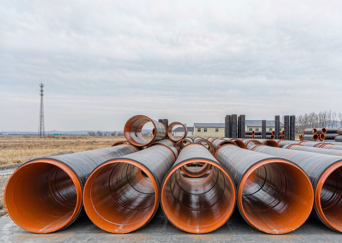
Large diameter clad pipes stacked in the yard with the stainless liner visible at the open ends Clad pipe · OD 25–2,134 mm
Structure

From plate to pipe,
without losing the bond.

Clad pipe starts from the same composite billet as our clad plate, then is formed and welded into a tube. Two metals are doing two clearly separate jobs.

OUTER
Carbon or low-alloy steel
API 5L X42–X80, Q235B, Q345B or 20G. This wall carries the internal pressure, the external soil and water load, and the longitudinal bending of a buried or subsea line — and it accounts for 70–90% of the wall weight.
INNER
Corrosion-resistant alloy
304 / 316L, duplex 2205 / 2507, or nickel alloys 825 / 625 / C-276. A 1–3 mm liner is normally enough, because its only job is to keep the medium and the carbon steel apart.
BOND
Metallurgical, not a push fit
The interface is fused at the atomic level. Shear strength is typically ≥210 MPa, comfortably above the 137.8 MPa floor set by API 5LD — so the liner cannot slip, buckle or collapse inside the carrier pipe.
ALLOY LINER 1–3 mm STEEL WALL 6–70 mm MEDIUM WALL BUILD-UP — WORKED EXAMPLE, DN300 2 mm 316L 8 mm API 5L X65
Before you specify

Metallurgical or mechanically bonded?

Both products are sold as “clad pipe” in the market, but they are not interchangeable. If your line runs at high pressure, carries sour service, or will be bent and buried, the difference decides whether the liner is still in place in ten years.

 Metallurgically bondedMechanically bonded (lined)
How it is made Composite billet, hot rolled, then formed and welded — or explosive welding of a liner Liner tube inserted and expanded hydraulically until it grips the carrier
Interface Atom-to-atom fusion across the full contact area Friction and interference fit only
Bond / shear strength ≥210 MPa shear, against the 137.8 MPa floor of API 5LD Friction only — no metallurgical shear value
Liner thickness 1–6 mm, selected to suit the duty 2–3 mm, limited by the expansion process
Counted in pressure design Yes — the composite wall carries load as one No — only the outer carrier is designed for pressure
Behaviour when bent Bends and forms with the pipe, no separation Risk of liner wrinkling, buckling and gap formation
Behaviour under thermal cycling Stable — expansion is matched across the bond Differential expansion can open the interface
Typical service High pressure, sour service, offshore, subsea, deep wells Medium and low pressure, onshore gathering and water lines
Relative cost Higher Lower

We manufacture and supply both. If a mechanical liner is genuinely sufficient for your duty we will say so — there is no reason to pay for a metallurgical bond you will never stress.

Why clad pipe

The corrosion performance of alloy,
at a fraction of the wall cost.

A solid alloy line is the simple answer, and for short runs of small diameter it is often the right one. Beyond a certain size and length, clad pipe wins on every measure that matters to a project.

01
Two metals, two jobs
The outer wall is sized for pressure, the inner wall for corrosion. Alloy is used only where it earns its keep.
02
Material cost down 30–50%
On a DN600 line, solid 316L is a wall of alloy. A clad line puts 2 mm of alloy inside 14 mm of X65 and does the same job.
03
Mechanical properties of carbon steel
Pressure rating, toughness and impact resistance follow the base steel grade. Laying, bending, burying and hydrostatic testing use standard carbon steel equipment and procedures.
04
A bond that stays closed
≥210 MPa shear against the 137.8 MPa floor of API 5LD — headroom that keeps the interface shut through thermal shock, bending and flattening.
05
Large diameters, fewer field joints
Solid alloy pipe becomes scarce and expensive above DN600. Clad pipe is made well past DN1200, in single lengths up to 12 m, which cuts field welds and installation time.
06
25 years and beyond
The alloy bore is immune to the general corrosion that would consume a carbon steel wall. Service life is set by the medium and the alloy, not by the pipe.
Service

Where clad pipe is working today

WELLHEAD sour wet gas GATHERING buried & bent PROCESSING high pressure STORAGE long service life GIRTH WELD GIRTH WELD FLOW MEDIUM TOUCHES ONLY THE ALLOY LINER the steel wall never sees the process fluid — it only sees pressure and soil SINGLE LENGTHS UP TO 12 m fewer field welds → faster installation, lower risk
Oil & gas gathering
Wet CO₂ and H₂S gathering lines, flowlines and trunk lines where carbon steel would corrode from the inside out.
316L / 2205 / 625 + X65
Subsea & deepwater
Flowlines, risers and water-injection lines where chloride stress corrosion cracking and weight both matter.
2507 / 625 / C-276 + X65
Petrochemical & refining
Overhead transfer lines, sour-water, amine and caustic circuits — small alloy requirement, long pipe runs.
316L / 825 / C-276
Desalination
High-pressure brine piping and reverse-osmosis seawater headers, where 316L would pit within a season.
2205 / 2507
Power & FGD
Absorber recirculation lines, limestone slurry and gypsum dewatering pipework.
316L / 2205 / C-276
Mining & tailings
Slurry and tailings transport where abrasion and corrosion arrive together; a wear alloy bore outlasts steel several times over.
Cr26 / 316L + Q235B
Choosing the liner

304 / 316L — general corrosion, food, water and dilute acids.  ·  2205 duplex — chlorides, seawater and brine.  ·  825 / 625 / C-276 — sour service, high temperature and aggressive acids. If you are unsure, send us the medium, the chloride level and the operating temperature and we will specify it for you.

Fittings & components

The whole line in one material

A clad line is only as good as its weakest component. We supply matching clad pipe fittings made from the same composite, so the alloy bore runs unbroken from end to end and there is no carbon steel exposed to the medium at a joint.
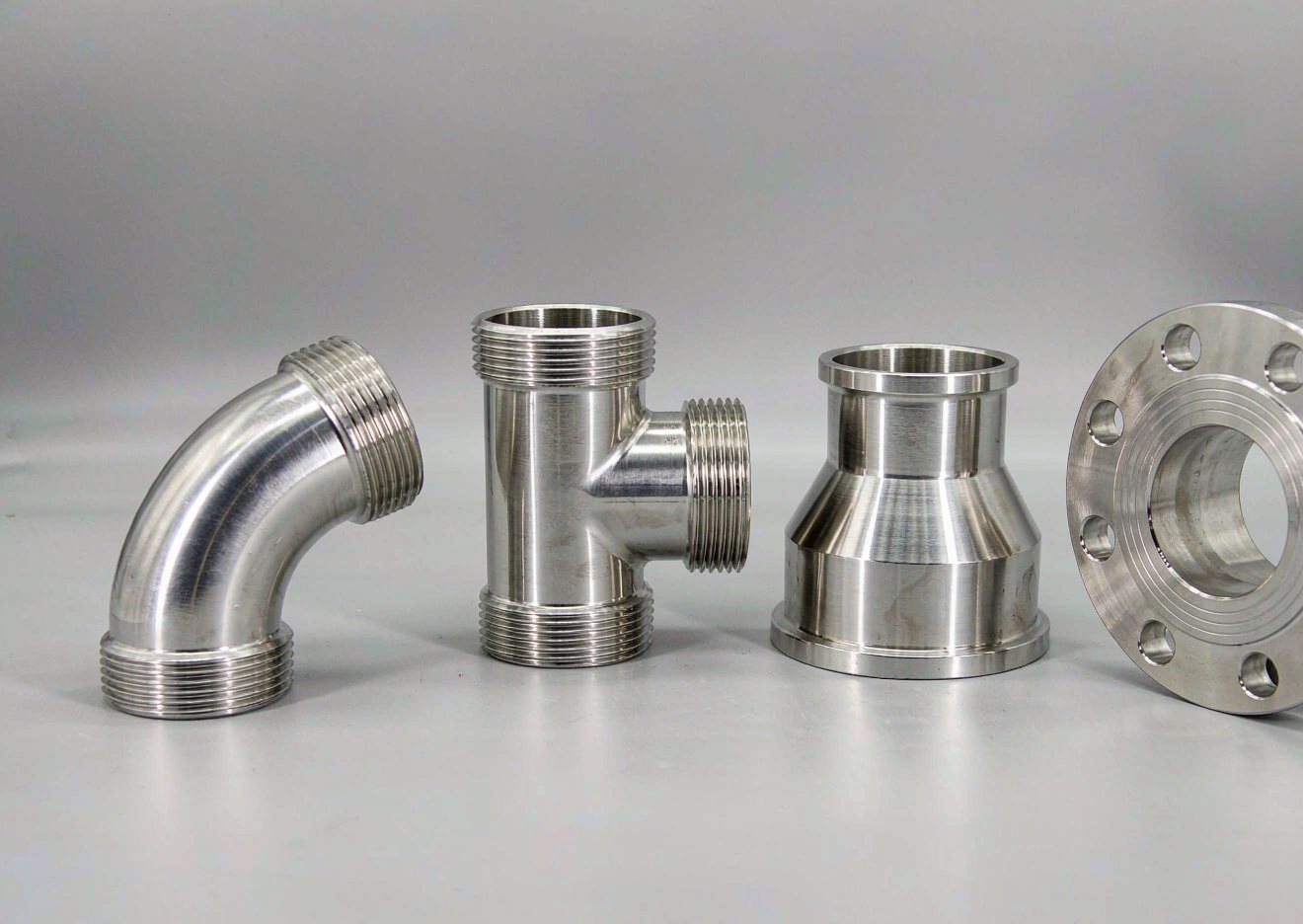
Clad pipe fittings - elbow, tee, reducer and flange Elbows · tees · reducers · flanges
Elbows
45°, 90° and 180° returns, long and short radius. The alloy bore follows the bend without wrinkling.
Tees
Equal and reducing tees, with the alloy layer continuous through the branch.
Reducers
Concentric and eccentric reducers, fabricated or formed from clad plate.
Flanges
Weld-neck, slip-on, blind and lap-joint flanges with a clad or weld-overlaid face.
Also available
Caps and stub ends · pipe bends and induction bends · swages · nozzles and manways · clad tube sheets · spools prefabricated to drawing
Weld-overlaid ends
Pipe ends can be faced with weld overlay so the bevel itself is alloy, protecting the joint area during site welding and giving the welder a stainless-to-stainless root.
Spool fabrication
We can prefabricate complete spools from clad pipe and fittings, welded, tested and dimensionally checked to your isometrics, so site work is reduced to girth welds.
Fabrication & installation

Handled like the carbon steel line
you already build

STEP 01
Bevel preparation
Standard 30° or 37.5° bevels machined on the pipe end. The alloy layer thickness governs the bevel face dimension, so the welder can see where the two metals meet.
STEP 02
Root pass
A corrosion-resistant root pass, usually with an alloy or nickel-base filler matched to the liner. Backing gas purges the bore so the internal surface is not oxidised.
STEP 03
Fill & cap
The remainder of the joint is filled with carbon steel filler using normal procedures, then capped so the external surface matches the carrier pipe.
STEP 04
Bending
Cold bending, induction bending and heat treatment are all acceptable. Keep the cladding on the compression side where geometry allows.
STEP 05
Inspection
Radiography or ultrasonic testing of girth welds, plus PMI on the root pass to confirm the alloy is correct. Hydrostatic test follows your line class requirement.
STEP 06
Field installation
Laying, lowering in, backfilling and tie-in use the same equipment as any carbon steel line. Only the root pass sequence is different.
Specification

Dimensions and standards

Range
Outer diameter25 – 2,134 mm
Wall thickness6 – 70 mm
Liner thickness1 – 6 mm
Single lengthup to 12 m
Bond shear strength≥210 MPa
Pressure designas composite wall
End finishplain, bevelled, weld-overlaid
Surfacebare, 3PE, FBE, epoxy lined
Standards
StandardCovers
API 5LDCRA-clad or lined steel pipe — the key international specification; shear strength floor 137.8 MPa
GB/T 31940Bimetal composite pipe for fluid service — Chinese national standard
SY/T 6623CRA composite pipe for oil and gas gathering and transmission
ASTM A928Ferritic/austenitic stainless steel pipe with added filler metal, electric fusion welded
ASTM A790 / A789Duplex and super duplex stainless steel pipe
DNV-OS-F101Submarine pipeline systems — offshore and subsea projects
NACE MR0175 / ISO 15156Materials for sour service; hardness limits and heat treatment

Dimensional ranges shown are the envelope we manufacture to. Confirm the exact combination with us before finalising your line class, and we will issue a material test certificate against the standard your project calls for.

Request a quote

Send us the line class
and we will size the pipe.

Medium, chloride level, operating pressure, temperature and length — that is enough for us to specify the liner and come back with a price. Isometrics and material take-offs welcome.

Mr. Cui — Sales Manager
+86 158 5280 5117
sales@xinleisteel.com